
What Is a Wiring Diagram?
A wiring diagram is a visual plan that shows how electrical conductors, devices, terminals, and power sources connect within a system. Symbols and labeled lines represent the physical or functional relationships between components. Electricians use the diagram to trace circuits, install equipment, verify connections, and diagnose faults in residential wiring.
Quick Facts About Wiring diagram
Category
Electrical documentation
Used for
Planning and tracing connections
Common confusion
Confused with a floor plan
Also called
Electrical wiring diagram, Wiring schematic
Often discussed with
Smart home wiring
Key Takeaways About Wiring diagram
- Symbols and lines show relationships between electrical components.
- The diagram supports installation, testing, and troubleshooting.
- A wiring diagram is not the same as a floor plan.
How Wiring diagram Works

Wiring diagram uses symbols, labels, and connecting lines to represent an electrical system. A line may identify a conductor between a power source, control, and load. Labels can show a terminal, switch position, wire function, or connection point. The drawing may describe physical locations, circuit logic, or both.
Related glossary terms: Smart switch, Neutral wire, Three-way switch.
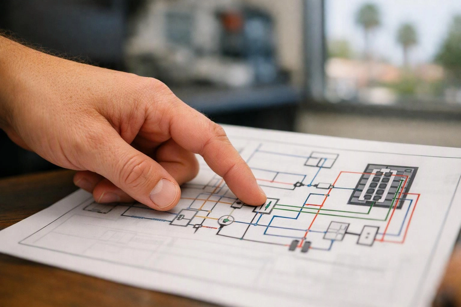
In smart home wiring, the diagram helps relate devices across a connected system. A technician can follow the path from a circuit to a smart switch and then to a light fixture. The diagram also shows where control wiring, neutral connections, and low-voltage communication paths meet. This view helps separate similar-looking conductors and supports testing during installation or troubleshooting.
From the Center Electric Service team
When we work on smart home wiring, we review the diagram against the devices and conductors present at the site. We trace each connection, check terminal labels, and note changes when the installed system differs from the planned layout.
Wiring diagram in Practice: A Real-World Example
A smart home wiring diagram can show a smart switch connected to a lighting load, neutral conductor, and control device. The diagram helps the installer identify each terminal before connecting the equipment.
Related Services
Related Terms
Smart switch
A smart switch is a wall-mounted control that operates lighting or other connected loads and communicates…
Neutral wire
Neutral wire is the grounded conductor that carries current back to the electrical panel after power…
Three-way switch
A three-way switch is a wall control that lets you operate one light or fixture from…
Junction box
Junction box is an enclosed electrical container that protects and organizes wire connections where circuits meet…
Center Electric Service
Have Questions About Wiring diagram?
Contact Center Electric Service for practical guidance on Wiring diagram and related electrical services work in Riverside.